Carnegie Mellon Racing · Driverless Controls
Regenerative Braking Control Design
Two ways to give the driver regen: put it under the accelerator, or add it to the brake pedal. I designed both, validated the first against a season of vehicle logs, and the team raced the second.
Parallel strategy on the car
Sept 2026 · Pittsburgh, PA · Regenerative Braking Lead
C (STM32 firmware) · Python · NumPy · Matplotlib · asammdf
Motivation
Regenerative braking turns speed back into battery charge instead of brake heat, which matters most in endurance, where efficiency is scored. The team also needed regen-heavy running early in the season to gather the data that informs the design of the 2027 car.
The previous design put regen on a steering-wheel paddle, and it had never worked on the car. Its throw was also awkward enough that pulling it fully meant moving your whole hand, mid-corner, while driving. The channel reads zero in all seven logs I checked, so there was nothing to build on and no baseline to beat.
That left two places regen could live: under the accelerator, where lifting off slows the car the way most electric road cars behave, or on the brake pedal, added on top of the hydraulics. I designed both. This post is about how each one works and why the team races the second.
One-Pedal: Rejected Approaches
My starting instinct was that the pedal should map to a target speed: compare it to the car’s actual speed and let a feedback controller decide the torque, which is how regen feels from the driver’s seat. It does not survive contact with the failure case. A velocity controller applies positive torque whenever the car is below the setpoint, so lifting the pedal in a slow corner would make the car accelerate. That is not a gain-tuning problem, it is inherent to the abstraction. Pedals map to torque, not speed.
The next suggestion on the table was to trigger regen on how fast the pedal is released. That makes torque a function of pedal history, so the same pedal position gives different torque depending on how you got there, and mid-corner, where the derivative goes to zero, regen either decays and the car surges at the apex, or you integrate back to a position map with extra steps and accumulated drift.
I also designed a conservative one-sided assist: estimate the speed the driver is asking for, and apply regen only while the car is above it. I wrote it up for a teammate, who pointed out it would be hard to tune, harder to validate, and confusing to drive, because regen stops when the estimate is reached while the driver’s foot has not moved. He was right, and it was the wrong thing to be building four days before a test.
The simplest version, regen whenever the pedal is released, needs a threshold, and replaying logs showed the pedal crossing any threshold hundreds of times a session. It only behaved with 0.15 s of hysteresis bolted on, which cut predicted regen episodes from 942 to 115 on one log. Splitting the pedal in half, regen below 50% and drive above, avoids the chatter, but the driver has to press past halfway just to pull away and the drive side loses half its resolution.
One-Pedal: Pedal Map Design
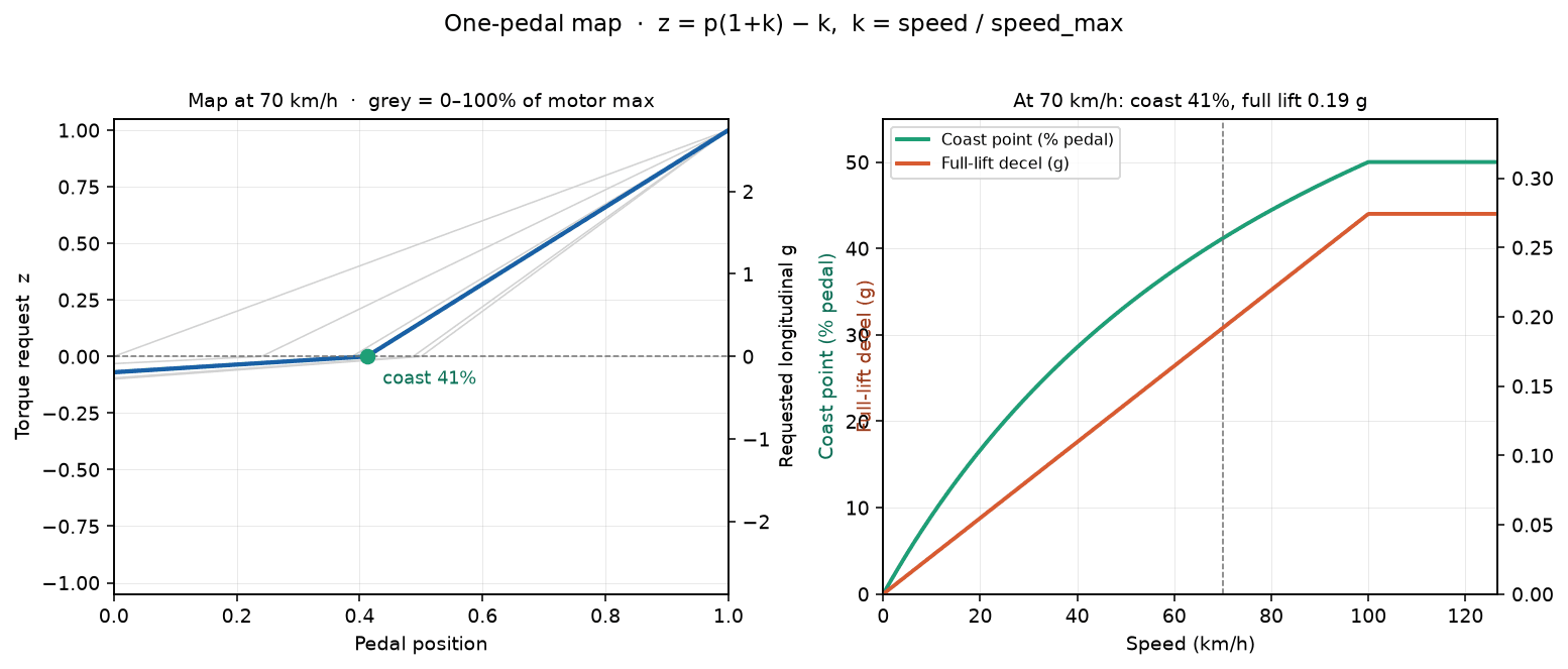
The final map moves the coast point, the pedal position where torque crosses zero, with speed:
z = p(1 + k) − k, k = clamp(avg motor RPM / regen_max_rpm, 0, 1)
p is pedal travel from 0 to 1, and z is the torque request from −1 to 1. Negative z is then scaled by a regen gain, which is the parameter that sets how hard the car actually decelerates; without it the map asks for up to 2.74 g at top speed, which the tires would have to refuse.
At a standstill k is 0, so z = p and the pedal behaves exactly as it always has. As the car speeds up, the coast point climbs toward half the pedal and a regen zone opens beneath it. Three useful properties come for free: regen fades to zero as the car stops, so it can never push the car backwards; full throttle always reaches full torque; and because the map passes straight through zero, pedal noise near the coast point barely changes the torque, so no hysteresis is needed. That last property is what the threshold design could not give me. Measured throttle dither at rest is two to three counts out of 255, which through this map is about 0.75 N·m on the drive side and 0.11 N·m on the regen side.
The speed that feeds k is average motor RPM, taken straight from the inverters, not the car’s estimated ground speed. The optical speed sensor spiked to 655 km/h in one log, and a speed source that can lie by a factor of six has no business setting how hard the car brakes. Motor RPM also clamps negatives to zero, so rolling backwards gives k = 0 and no regen. The clamp sits inside the k calculation deliberately: a NaN or infinite speed collapses to k = 0, which is today’s behaviour, instead of collapsing to full regen.
Validation Against Logged Data
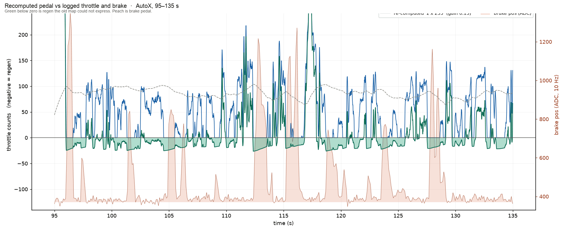
Before it went anywhere near the car, I replayed logged sessions through the same function in Python. Throttle, brake position, and per-motor RPM go onto a common 100 Hz grid, and average motor RPM is rebuilt the way the firmware computes it. The replay answers one primary question: when the driver actually braked, would regen already have been on? On an autocross run, yes for 99.8% of braking time, and 96.6% on a September test session. In the window below, requested deceleration peaks at 0.28 g, well within what the tires can take.
That coverage number is the trustworthy one, and it is still an upper bound. The replay assumes the driver’s foot does what it did under the old pedal map, and under the new one they would press further for the same torque, so how often regen engages is optimistic. The reason coverage is high at all is mundane: a driver about to brake is already off the throttle. Even with the coast point at zero, 92.4% of braking time on the autocross log already has the pedal fully released.
Parallel Regen and Strategy Selection
The other strategy keeps the brake pedal as the driver’s request and adds regen torque on top of it, proportional to how hard they are braking. The friction brakes are untouched: on this car they are purely hydraulic and never mediated by software, so regen can only ever add deceleration to what the driver already asked for. Nothing I write can reach the brakes.
That property is why parallel is the strategy we went forward with. The genuinely hard problem in production EV braking is blending, where the pedal requests a deceleration and the car decides how much comes from regen and how much from friction, with the handoff invisible to the driver. We do not have to solve it. Parallel regen recovers less energy than a blended system, but it cannot surprise the driver and it cannot fail into a dangerous state.
It also behaves exactly as designed in the data. Across a full testing day, regen torque appeared for 4.49 s with the brake applied and 0.00 s without it, scaling with brake pressure: around −1.13 N·m at light pedal, 20 to 150 psi, and about −13.28 N·m above 700 psi.
One-pedal is the more interesting control problem and parallel is the better answer for a car that has to pass scrutineering and be handed to a driver with twenty minutes of practice. Both designs are mine; only one of them races.
Scope and Downstream Systems
Neither strategy touches the brakes, and neither decides how torque reaches the ground. Each one produces a dimensionless request that feeds the existing four-corner torque allocator, which splits torque across the motors within each tire’s grip limit using a tire model fed by live downforce measurements, and blocks regen entirely when the battery cannot accept charge. I did not build the allocator or the tire model; my work sits upstream of them.
That boundary is why the request can be aggressive without being dangerous, and it is also why the next question became unavoidable: the map asks for a fraction of available torque, but nobody could say how much deceleration a given amount of regen torque actually produces on this car. Measuring that became the second half of the project.